
Arduino Compatible MC-2100 Controller and Lathe Tachometer
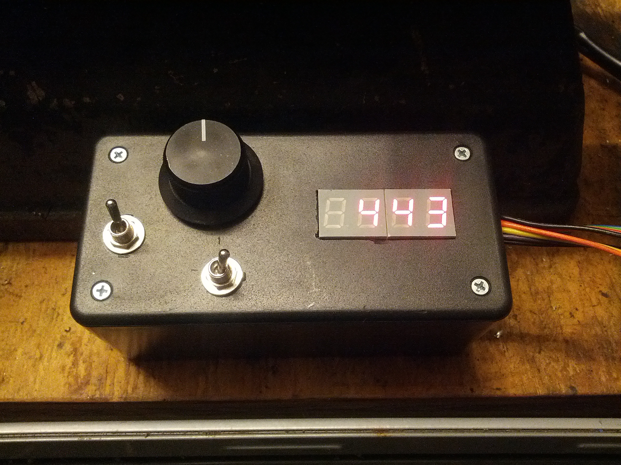
The completed circuit in operation
After getting the simple 555 based MC-2100 driver circuit working, we moved on to a controller with more features. I’d been looking for an excuse to make an arduino-compatible board (here’s a description if you’re not familiar), and this seemed like the ticket.
The initial spec for the controller included the following functions:
- Read user input from potentiometer
- Send the 50ms period PWM signal to the MC-2100
- Sense the lathe’s spindle speed using a magnetic reed switch or equivalent
- Display the spindle speed on a 7 segment LED display
At this point, the controller meets the requirements laid out above. I’ll discuss the implementation of each feature into the controller in the order listed above.
Read User Input
This is fairly simple. The potentiometer is set up as a voltage divider, with the wiper connected to an analog pin on the ATMega328p. A simple bit of code removes the jitter from the reading, only taking a new value once the reading changes by a threshold value. This reduces the resolution, but it’s still more than enough for my purposes.
 //Read and condition pot value
 potTemp = analogRead(POT_READ);
 potCheck = abs(potTemp - potValue);
 if(potCheck >= POT_DIF) { //Only accept new value if it's far enough from the current accepted value
 potValue = potTemp;
 }
I ended up adding an on/off switch to the input as well, so that the lathe can be stopped and restarted at the same speed. For this, I used a debounce function that Joe and I had developed for one of his guitar pedal projects. It watches an input, and waits until it’s steady for a certain amount of time (TO_HIGH_DELAY or TO_LOW_DELAY) before changing the output.
Here’s the function declaration:
////////////////////////////////////////////////////////////////////////////////////////////
/* Function for debouncing digital inputs

 Arguments:
 _debouncePin - ID of pin to be read/debounced
 *lastReading - pointer to variable storing the previous reading (HIGH/LOW) of the input pin
 *lastDebounceTime - pointer to variable storing the last time (ms) the input changed (not debounced)
 _toLowDelay - debounce time for HIGH to LOW transition
 _toHighDelay - debounce time for LOW to HIGH transition

 Returns:
 _state - debounced state (HIGH/LOW) of _debouncePin
 */
////////////////////////////////////////////////////////////////////////////////////////////

byte debounce(byte _debouncePin, byte *lastReading, unsigned long *lastDebounceTime, int _toLowDelay, int _toHighDelay)
{
 byte _reading = digitalRead(_debouncePin);
 byte _state = *lastReading;

if (_reading != *lastReading) { // pin state just changed
 *lastDebounceTime = millis(); // reset the debouncing timer
 }

if ((millis() - *lastDebounceTime) >= _toLowDelay && _reading == LOW) {
 // whatever the reading is at, it's been there for longer
 // than the hold delay, so take it as the actual current state for use in the rest of the script
 _state = _reading;
 *lastReading = _reading;
 return _state;
 }

if ((millis() - *lastDebounceTime) >= _toHighDelay && _reading == HIGH){
 // whatever the reading is at, it's been there for longer
 // than the hold delay, so take it as the actual current state for use in the rest of the script
 _state = _reading;
 *lastReading = _reading;
 return _state;
 }
 *lastReading = _reading;
 return _state;
}
And the function call:
onOffState = debounce(ON_OFF, &lastonOffState, &lastOnOffTime, TO_LOW_DELAY, TO_HIGH_DELAY);
The result is passed through a simple IF statement to decide whether to send a speed command to the MC-2100 or not.
Send 50ms PWM to MC-2100
I wasn’t sure how to do this one at first. We started by hardcoding the pwm signal using millis() and conditional statements. It worked, but I figured there had to be a cleaner way. I eventually discovered the Timer1 Library, which worked perfectly for our purposes. After adding the library to my arduino installation, it was a cinch to get the signal sent to the MC-2100.
The PWM is initialized like this:
Timer1.initialize(PWM_CYCLE*1000); //Set pin 9 and 10 period to 50 ms

Timer1.pwm(PWM_OUT, 0); //Start PWM at 0% duty cycle
Where PWM_CYCLE is the desired period in milliseconds, and PWM_OUT is the output pin.
The PWM duty cycle is then updated like this, including the if statements for ON/OFF functionality:
//Send output signal only if ON/OFF switch is in ON position
 if (onOffState == LOW){ //Off
 Timer1.setPwmDuty(PWM_OUT, 0); //Shut down MC-2100
 }

if (onOffState == HIGH){ //ON
 Timer1.setPwmDuty(PWM_OUT, speedLevel); //Send speed command to MC-2100
 }
With that small amount of code, we can control the MC-2100’s speed level just like the simple circuits from earlier posts. Now it’s time to get the speed readout working.
Sense Spindle Speed
In order to sense the spindle speed of the lathe, I attached two neodymium magnets (I’ll discuss the lathe setup in a future post) and placed a reed switch nearby to pick up when they go past. The reed switch is connected to a simple conditioning circuit as follows:
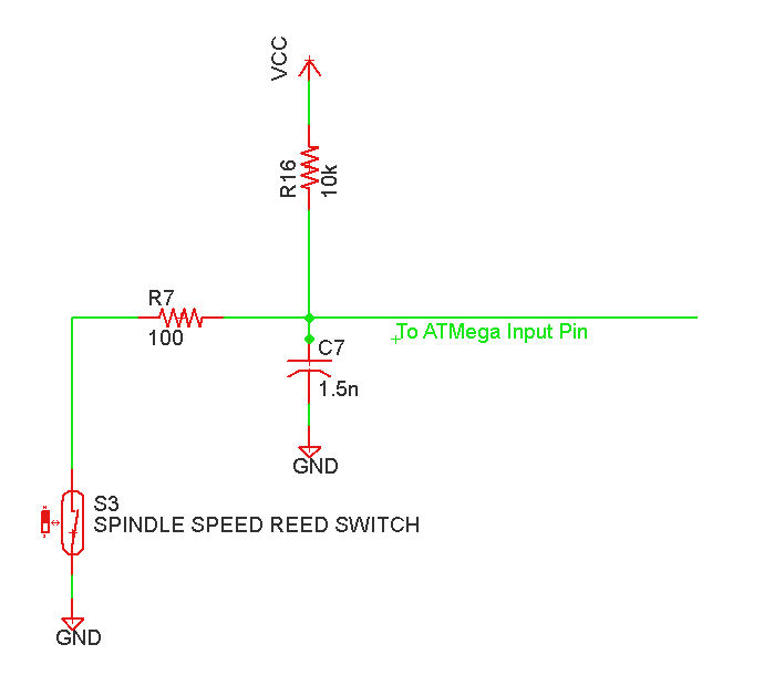
Reed Swtich Input Low Pass Filter Circuit
This circuit includes a pull up resistor (R16) and a low pass filter (R7 and C7) to condition the reed switch and send it to the ATMega’s input pin.
To read the signal with the Arduino, I used one of the ATMega’s external interrupts to ensure that I never missed a pulse. The interrupt is initialized as follows:
attachInterrupt(0, intervalCalc, FALLING); //Attach interrupt to pin 2 for spindle speed sensing
Where intervalCalc is the Interrupt Service Routine, the function that gets called each time the interrupt is triggered. Here’s the function definition:
////////////////////////////////////////////////////////////////////////////////////////////
void intervalCalc() //Interrupt Service Routine - Store time interval from reed switch each magnet pulse
{
 if ((millis() - reedTime) >= REED_DELAY) { //ignore switch bounce for (REED_DELAY) ms (not the normal debounce routine)
 if (reedTime !=0) { //Is this the first interrupt since reset?
 reedSet = 1; //set flag
 reedInterval = millis() - reedTime; //calculate interval
 }
 reedTime = millis(); //record last interrupt time
 }
}
To keep the ISR as short as possible, it only records the time it was entered, and checks and resets a couple flags for use in the main body of the code.
The reedInterval value from the ISR is then recorded, averaged, smoothed, and converted to RPM in the main() function.
if (reedSet == 1) { //Interrupt triggered since last loop, calculate RPM
 reedSet = 0; //reset interrupt flag
 intervalCount++; //increment counter (used for averaging first few pulses)

//Store interval from ISR in vector for averaging
 for(int n=NUM_SAMPLES-1; n>0; n--) {
  intervals[n]=intervals[n-1]; //Shift all values to the right. Oldest value discarded
 }
 intervals[0] = constrain(reedInterval,0,RESET_DELAY); //new value at beginning of vector

//Caculate RPM
 intervalSum = 0; //reset sum value
  for(int n=0; n<NUM_SAMPLES; n++) { intervalSum += intervals[n]; //add intervals together
 }
 avgInterval = intervalSum/min(intervalCount,NUM_SAMPLES); //calculate average interval
 rawSpindleSpeed = 60000/(avgInterval); //convert to RPM
 spindleSpeed = smooth(rawSpindleSpeed, SMOOTH_LEVEL, spindleSpeed); //smooth RPM reading
 Multiplex7SegGen::loadValue(spindleSpeed); // display measured RPM on 7 segment
}
I added in a reset function to reset the display to zero quickly once the spindle stops. With only two magnets on the spindle, there can be quite a bit of time between inputs. This limits the minimum readable speed to around 40 RPM.
if ((millis() - reedTime) >= RESET_DELAY) { //If no pulses received for (RESET_DELAY) ms, reset all counters/intervals
 for(int n=0; n<NUM_SAMPLES; n++) {
  intervals[n] = 0;
  intervalCount = 0;
  reedTime = 0;
  spindleSpeed = 0;
  pendingDecel = LOW; //The spindle has stopped, OK to reverse direction. (Not used yet)
 }
 Multiplex7SegGen::loadValue(0); // reset display to 0 RPM
}
That wraps up the speed sensing circuit. On to the 7 segment display!
Display Spindle Speed on LED Display
For the display portion of the build, I used a couple two digit 7 segment displays from a treadmill’s dash panel. A brief overview of interfacing 7 segment displays with Arduino can be found here. Like most microcontroller topics, this one has two parts: the hardware and the software. For the hardware, I built a fairly standard 7 segment display circuit, with one exception. My displays were common anode (all the LED’s in the display share their positive pin), while most are common anode cathode. This meant that instead of pulling the cathodes down through NPN transistors, I pulled the anodes up with PNP transistors. Simple enough, right?
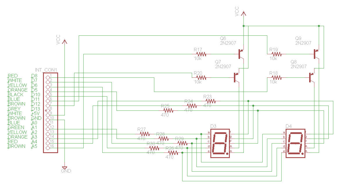
7 Segment Display Circuit
The software side of things was almost really easy… There are a few different 7 segment libraries available for arduino that have all the functionality required for this display. The only problem is that the best one I found was set up for common cathode displays instead of common anode, so the display would be inverted. I ended up learning how libraries worked, which wasn’t a bad thing, and modified an existing library to accept different display types. The modified library can be downloaded here if you’re interested.
With the library ready to go, all that was left was inserting the proper commands into the code. The display is initialized like this:
#define D1 8 //7 segment Digit Selection Pins
#define D2 11
#define D3 12
#define D4 A5
#define S1 A2 //7 segment Segment Selection Pins
#define S2 A1
#define S3 7
#define S4 10
#define S5 6
#define S6 A3
#define S7 A4
#define S8 5

......

byte digitPins[] = {
  D1,D2,D3,D4};
byte segmentPins[] = {
  S1,S2,S3,S4,S5,S6,S7};

......

void setup()
{

......

Multiplex7SegGen::set(1, 4, digitPins, segmentPins, LOW, LOW); // initialize 7 segment library as common anode

.....

}
If I were using a common cathode display, the last two arguments would be HIGH, HIGH. The source library had these values hard coded in the .cpp file.
Updating the display is simple as well:
Multiplex7SegGen::loadValue(spindleSpeed); // display measured RPM on 7 segment
Future Plans
I’m pretty happy with the controller as it stands today. It’s made my lathe much easier to use, and enabled the use of a more refined motor controller than I was using previously.
To take things a step farther, I’d like to add an external reversing/braking circuit to the MC-2100, using the Arduino to control a relay H Bridge with a dynamic braking resistor. The second switch you see on the input panel will be used to select forward and reverse, and I’ll build a relay circuit that goes between the MC-2100 and the lathe motor. That will have to wait till I get a few more projects out of the way though…
Summary
Gut Shot:
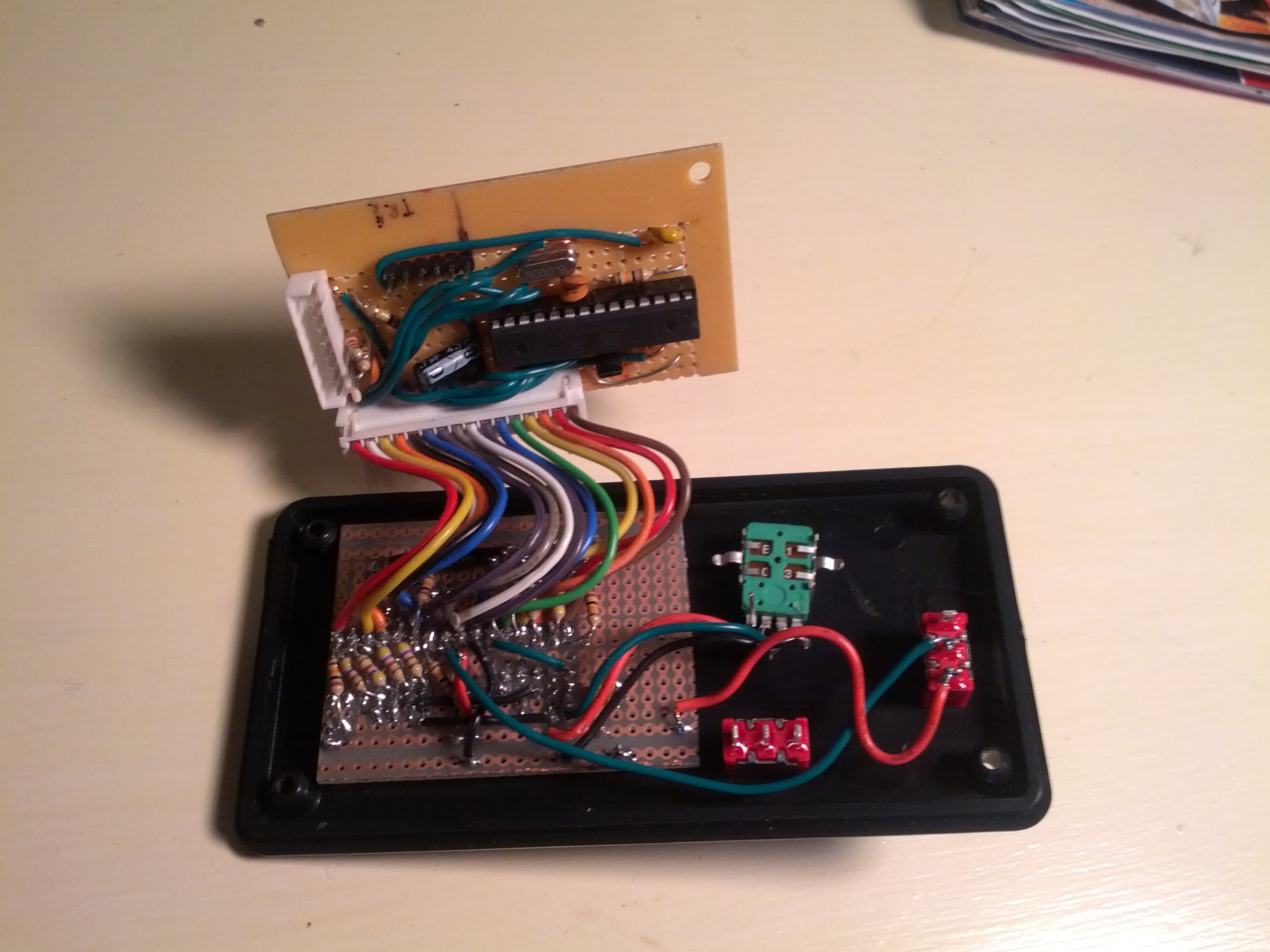
Internals. In this picture, the arduino portion is on the upper board, and the 7 segment display and user inputs are on the lower.
Here’s the full schematic, including the arduino circuitry and the 7 segment display (click here to download the Eagle file)::
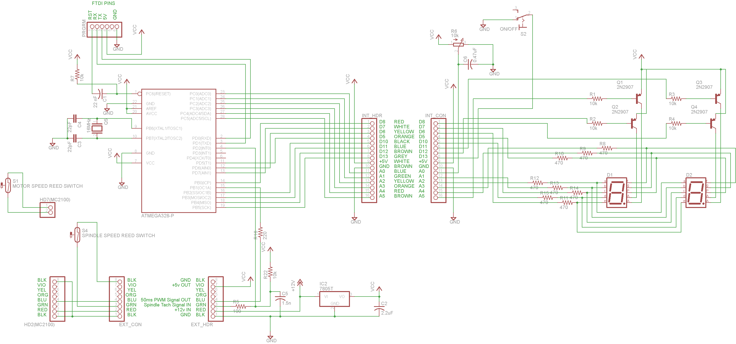
Arduino Compatible MC-2100 Controller and Tachometer
And the full arduino code (click here to download):
/*
 MC-2100 Treadmill Motor Controller Interface
 Lathe Motor Controller via PWM
 Seven Segment Tachometer
 ON/OFF Toggle

 Joe Schoolcraft
 Brian Schoolcraft
 May 2013
 https://sonsofinvention.wordpress.com/
*/
#include  //Modified from here: http://code.google.com/p/mutiplex7seg/ (adapted to work with any 7 segment display type, mine is common anode)
#include  //http://playground.arduino.cc/code/timer1

#define POT_READ A0 //Wiper of pot connected as voltage divider (Speed Command Input)
#define SPEED_SENSE 2 //connected to reed switch - magnet closes switch, pulls to ground (Spindle Speed Input - 2 pulses per rev)
#define PWM_OUT 9 //Connected to blue wire of MC2100 (50ms period PWM out)
#define REV_OUT 1 //Reverse Relay Output (Not Used)
#define FWD_OUT 0 //Forward Relay Output (Not Used)
#define FWD_REV 3 //Fwd/Rev Switch Input (Not Used)
#define ON_OFF 13 //On/Off Switch Input

#define PWM_CYCLE 50.0 //Output Signal PWM Period (50ms)

#define POT_DIF 4 //Change detection threshold on pot
#define MAX_DUTY 869 //Max Duty Cycle expected by MC-2100 (85% of 1023)
#define MIN_DUTY 0 //Min Duty Cycle expected by MC-2100 (0% of 1023)
#define REED_DELAY 20 //Deboounce time for reed switch
#define RESET_DELAY 1000 //Time delay before resetting speed to 0
#define NUM_SAMPLES 2 //Number of Samples to average before smoothing function
#define SMOOTH_LEVEL 0.5 //Input to smoothing function
#define TO_LOW_DELAY 50 //Debounce time for HI to LO switch transition
#define TO_HIGH_DELAY 50 //Debounce time for LO to HI switch transition

#define D1 8 //7 segment Digit Selection Pins
#define D2 11
#define D3 12
#define D4 A5
#define S1 A2 //7 segment Segment Selection Pins
#define S2 A1
#define S3 7
#define S4 10
#define S5 6
#define S6 A3
#define S7 A4
#define S8 5

int potTemp;
int potValue;
int lastPotValue;
int potCheck;
int speedLevel;

byte digitPins[] = {
 D1,D2,D3,D4};
byte segmentPins[] = {
 S1,S2,S3,S4,S5,S6,S7};

long intervals[NUM_SAMPLES] = {0,0}; //Last NUM_SAMPLES reedInterval values for averaging spindle speed
long intervalSum; //Sum of intervals vector
int avgInterval; //Averaged interval value
int spindleSpeed = 0; //Spindle speed converted from avgInterval and smoothed
int rawSpindleSpeed = 0; //Spindle speed converted from avgInterval
int intervalCount = 0;

unsigned long lastFwdRevTime = 0;
unsigned long lastOnOffTime = 0;
byte reading = 0;
byte fwdRevState = 0;
byte onOffState = 0;
byte lastfwdRevState = 0;
byte lastonOffState = 0;
byte pendingDecel = 0;

//ISR Variables stored as volatile (kept in RAM)
volatile unsigned long reedTime = 0; //Last time reed switch closed
volatile unsigned long reedInterval; //Time since last reed switch closure
volatile boolean reedSet = 0; //Reed switch tracker

void setup()
{
 pinMode(POT_READ, INPUT);
 pinMode(PWM_OUT, OUTPUT);
 pinMode(SPEED_SENSE,INPUT);

pinMode(ON_OFF, INPUT_PULLUP); //Enable internal pullup resistor to simplify external circuit

Multiplex7SegGen::set(1, 4, digitPins, segmentPins, LOW, LOW); // initialize 7 segment library as common anode

attachInterrupt(0, intervalCalc, FALLING); //Attach interrupt to pin 2 for spindle speed sensing

Timer1.initialize(PWM_CYCLE*1000); //Set pin 9 and 10 period to 50 ms
 Timer1.pwm(PWM_OUT, 0); //Start PWM at 0% duty cycle
}

void loop()
{
 //Read and condition pot value
 potTemp = analogRead(POT_READ);
 potCheck = abs(potTemp - potValue);
 if(potCheck >= POT_DIF) { //Only accept new value if it's far enough from the current accepted value
 potValue = potTemp;
 }

 speedLevel = map(potValue,0,1023,0,MAX_DUTY); //Convert Pot input to pwm level to send to MC-2100

//Read and Debounce Switches
 //Not Used Yet fwdRevState = debounce(FWD_REV, &lastfwdRevState, &lastFwdRevTime, TO_LOW_DELAY, TO_HIGH_DELAY);
 onOffState = debounce(ON_OFF, &lastonOffState, &lastOnOffTime, TO_LOW_DELAY, TO_HIGH_DELAY);
 //Send output signal only if ON/OFF switch is in ON position
 if (onOffState == LOW){ //Off
 Timer1.setPwmDuty(PWM_OUT, 0); //Shut down MC-2100
 }

if (onOffState == HIGH){ //ON
 Timer1.setPwmDuty(PWM_OUT, speedLevel); //Send speed command to MC-2100
 }

////////////////////////////////////////////////////////////////////////////////////////////
 ////////////////////////////////////////////////////////Relays/Braking not implemented at this time
 // //Set Relay States and MC-2100 PWM Levels
 //
 // if (fwdRevState != lastfwdRevState){ //The direction switch has been flipped
 // pendingDecel = HIGH; //Set decel flag. This gets reset low once the spindle stops
 // }
 //
 // if (onOffState == LOW){ //Off
 // digitalWrite(FWD_OUT, LOW); //Set relays for braking
 // digitalWrite(REV_OUT, LOW);
 // Timer1.setPwmDuty(PWM_OUT, 0); //Shut down MC-2100
 // }
 //
 // if (onOffState == HIGH){ //On
 // if (pendingDecel == LOW){
 // if (fwdRevState == HIGH){ //Fwd
 // digitalWrite(FWD_OUT, HIGH); //Set relays for FWD operation
 // digitalWrite(REV_OUT, LOW);
 // Timer1.setPwmDuty(PWM_OUT, speedLevel); //Send speed command to MC-2100
 // }
 // if (fwdRevState == LOW){ //Rev
 // digitalWrite(FWD_OUT, LOW); //Set relays for REV operation
 // digitalWrite(REV_OUT, HIGH);
 // Timer1.setPwmDuty(PWM_OUT, speedLevel); //Send speed command to MC-2100
 // }
 // }
 // else{
 // digitalWrite(FWD_OUT, LOW); //Set relays for braking
 // digitalWrite(REV_OUT, LOW);
 // Timer1.setPwmDuty(PWM_OUT, 0); //Shut down MC-2100
 // }
 // }
 ////////////////////////////////////////////////////////////////////////////////////////////

 //Calculate RPM from interrupt routine output, display on 7 segment

if (reedSet == 1) { //Interrupt triggered since last loop, calculate RPM
 reedSet = 0; //reset interrupt flag
 intervalCount++; //increment counter (used for averaging first few pulses)

//Store interval from ISR in vector for averaging
 for(int n=NUM_SAMPLES-1; n>0; n--) {
 intervals[n]=intervals[n-1]; //Shift all values to the right. Oldest value discarded
 }
 intervals[0] = constrain(reedInterval,0,RESET_DELAY); //new value at beginning of vector

//Caculate RPM
 intervalSum = 0; //reset sum value
 for(int n=0; n<NUM_SAMPLES; n++) {  intervalSum += intervals[n]; //add intervals together  } avgInterval = intervalSum/min(intervalCount,NUM_SAMPLES); //calculate average interval rawSpindleSpeed = 60000/(avgInterval); //convert to RPM  spindleSpeed = smooth(rawSpindleSpeed, SMOOTH_LEVEL, spindleSpeed); //smooth RPM reading Multiplex7SegGen::loadValue(spindleSpeed); // display measured RPM on 7 segment  } if ((millis() - reedTime) >= RESET_DELAY) { //If no pulses received for (RESET_DELAY) ms, reset all counters/intervals
 for(int n=0; n<NUM_SAMPLES; n++) {  intervals[n] = 0;  intervalCount = 0;  reedTime = 0;  spindleSpeed = 0;  pendingDecel = LOW; //The spindle has stopped, OK to reverse direction. (Not used yet)  }  Multiplex7SegGen::loadValue(0); // reset display to 0 RPM  } } //////end loop //////////////////////////////////////////////////////////////////////////////////////////// void intervalCalc() //Interrupt Service Routine - Store time interval from reed switch each magnet pulse {  if ((millis() - reedTime) >= REED_DELAY) { //ignore switch bounce for (REED_DELAY) ms (not the normal debounce routine)
 if (reedTime !=0) { //Is this the first interrupt since reset?
 reedSet = 1; //set flag
 reedInterval = millis() - reedTime; //calculate interval
 }
 reedTime = millis(); //record last interrupt time
 }
}

////////////////////////////////////////////////////////////////////////////////////////////
/* Function for debouncing digital inputs

 Arguments:
 _debouncePin - ID of pin to be read/debounced
 *lastReading - pointer to variable storing the previous reading (HIGH/LOW) of the input pin
 *lastDebounceTime - pointer to variable storing the last time (ms) the input changed (not debounced)
 _toLowDelay - debounce time for HIGH to LOW transition
 _toHighDelay - debounce time for LOW to HIGH transition

 Returns:
 _state - debounced state (HIGH/LOW) of _debouncePin
 */
////////////////////////////////////////////////////////////////////////////////////////////

byte debounce(byte _debouncePin, byte *lastReading, unsigned long *lastDebounceTime, int _toLowDelay, int _toHighDelay)
{
 byte _reading = digitalRead(_debouncePin);
 byte _state = *lastReading;

if (_reading != *lastReading) { // pin state just changed
 *lastDebounceTime = millis(); // reset the debouncing timer
 }

if ((millis() - *lastDebounceTime) >= _toLowDelay && _reading == LOW) {
 // whatever the reading is at, it's been there for longer
 // than the hold delay, so take it as the actual current state for use in the rest of the script
 _state = _reading;
 *lastReading = _reading;
 return _state;
 }

if ((millis() - *lastDebounceTime) >= _toHighDelay && _reading == HIGH){
 // whatever the reading is at, it's been there for longer
 // than the hold delay, so take it as the actual current state for use in the rest of the script
 _state = _reading;
 *lastReading = _reading;
 return _state;
 }
 *lastReading = _reading;
 return _state;
}
///////////////////////////////////////////////////////////////Function for smoothing sensor readings: http://playground.arduino.cc//Main/Smooth
int smooth(int data, float filterVal, int smoothedVal){

if (filterVal > 1){ // check to make sure param's are within range
 filterVal = .99;
 }
 else if (filterVal <= 0){
 filterVal = 0;
 }

smoothedVal = (data * (1 - filterVal)) + (smoothedVal * filterVal);

return (int)smoothedVal;
}

Grant Brown 8:44 am on May 28, 2013 Permalink |
Hey, thanks for this. I had a broken treadmill in my basement with one of these controllers in it, and your blog was the only info I could find on the pinout of the MC2100.
richard caput 4:05 pm on September 2, 2014 Permalink |
Excellent job on all this man, ive been hunting alot of similar topics to you as i have seen your digital “breadcrumbs” all over the web from you hunting down a burnt out resistor to your footpedal mod and now this work of art up there, looks awesome man but i suck at electronics and all i want to do is get my effn atlas 10″ spinning on this 2.5hp, i ran it on an mc60 for awhile, fried after a month, ran another mc60 burnt in 2 weeks, stumbled across an mc2100, circuit board got cracked in my backpack leaving the dump B^D , ordered arduino and as soon as it got here hooked it up to the mc2100 (arduino to wall wart, uploaded all your code to arduino and jujst deleted multiplexing call the kept halting compile, hooked both to common ground, red wire to 100k pot, wiper to A0, .47ceramic wiper to G, and like magic the arduino temporarily dissapeared in a puff of smoke. threw it in corner and ordered another. so here i sit with another arduino a whole lot of parts and im hoping you will tell me a very simple way i can hook a pot to this arduino andthe mc2100 and fill my atlas with no more than 120vDC Brush burning Fury! seriously though real paranoid to screw this up again, just need my damn lathe running so i can start hammering out my todo list.
schoolie 1:37 pm on September 8, 2014 Permalink |
I think this circuit should work with the code you’ve already used. You should be able to run it by simply commenting out the multiplex7seg library as you have before. You’ll notice the arduino is getting its power and ground from the MC2100 directly, it shouldn’t be plugged in to the wall or the USB port any time the MC2100 is plugged in.
Bigger Version…
The on/off switch on pin 13 should be optional, I’m pretty sure it defaults to ON if nothing is connected.
In an attempt to diagnose your earlier problem, when you say you hooked the red wire to the pot, do you mean the red wire from the MC2100? If so, depending on the position of your potentiometer, you may have applied 12v to the analog pin of the arduino, which could cause the smoke you mentioned :). The pot needs to be hooked up between a 5v source and ground, as shown in my schematic.
Let me know if you have any more questions. Good luck!
Richard Caput 7:09 pm on September 10, 2014 Permalink |
Wow, thanks man this actually worked without me frying anything, i think it also goes down as my first time being truly thankful to anyone whos schooled me over the internet. My best regards to you and if you ever need a part run thats too big for your RF i work for a machinist who gives me time on his jet bridgeport clone shoot me an email and ill try to repay the favor.
btw, i did hook the red from mc2100 to the arduino, i think the chip is fine but the board is shot, got a cheap chinese knockoff for $4.00 on ebay and other than the $26 still in my wallet it seems to me identical… Cheers!
Richard Caput 7:25 pm on September 10, 2014 Permalink |
Also! i have a few real pretty SKF AC (reversible) gearmotors from an invacare hospital bed identical to this http://tinypic.com/r/dxflup/8 do you see any reason why i couldnty drive this motor with the incline circuit from the mc2100 and can you think of a way i could control the speed? i would like to use it to drive my leadscrew instead of this prehistoric rubics cube of a gearbox with the atlas? I use two of these motors for powerfeed on my RF clone at home with the hospital bed controller 🙂 so they are more than powerful enough i just dont want to fry the MC by putting too much (current)? through it. thanks again!
schoolie 11:25 am on September 11, 2014 Permalink |
I’m glad that worked for you! Happy to help.
I’d guess you could simply connect your motor to the incline motor terminals. The incline motor on the treadmill is a small reversible AC motor (I think). Current rating… no idea. If it does fry something, that part of the circuit is independent of the main motor circuit, so you should be OK. Never tried it though, so do so at your own risk 🙂
To control the motor direction, I’m pretty sure applying 5v to pin 5 or 6 of the MC2100 connector (orange and yellow wires) one at a time will select fwd or rev. You can see the incline motor circuit in the MC2100 schematic (left-center) at the bottom of this post.
chris 5:18 am on June 16, 2017 Permalink |
hi as a new arduino user, can you explain what you mean by comment out multiplex 7seg? do i find all headings with this and erase? thanks chris
Patrick Nolan 4:18 pm on May 29, 2016 Permalink |
This circuit worked great with my 2100E board, i used a very chopped down code, variable pot, works perfectly to control on off state of relay in my emi device, and speed, thanks very much for this post, i was a bit frustrated with trying to get the board to operate. hope this helps somebody else.
#include
/*
MC-2100 Treadmill Motor Controller Interface
Lathe Motor Controller via PWM
Seven Segment Tachometer
ON/OFF Toggle
Joe Schoolcraft
Brian Schoolcraft
May 2013
https://sonsofinvention.wordpress.com*/
#define POT_READ A0 //Wiper of pot connected as voltage divider (Speed Command)
#define PWM_OUT 9 //Connected to blue wire of MC2100 (50ms period PWM out)
#define ON_OFF 13 //On/Off Switch Input
#define PWM_CYCLE 50.0 //Output Signal PWM Period (50ms)
#define POT_DIF 4 //Change detection threshold on pot
#define MAX_DUTY 869 //Max Duty Cycle expected by MC-2100 (85% of 1023)
#define MIN_DUTY 0 //Min Duty Cycle expected by MC-2100 (0% of 1023)
int potTemp;
int potValue;
int lastPotValue;
int potCheck;
int speedLevel;
byte onOffState = 0;
void setup()
{
pinMode(POT_READ, INPUT);
pinMode(PWM_OUT, OUTPUT);
Timer1.initialize(PWM_CYCLE*1000); //Set pin 9 and 10 period to 50 ms
Timer1.pwm(PWM_OUT,25); //Start PWM at 0% duty cycle
}
void loop()
{
//Read and condition pot value
potTemp = analogRead(POT_READ);
potCheck = abs(potTemp – potValue);
if(potCheck >= POT_DIF) { //Only accept new value if it’s far enough from the current accepted value
potValue = potTemp;
}
speedLevel = map(potValue,0,1023,0,MAX_DUTY); //Convert Pot input to pwm level to send to MC-2100
if (onOffState == LOW){ //Off
Timer1.setPwmDuty(PWM_OUT, speedLevel); //Shut down MC-2100
}
if (onOffState == HIGH){ //ON
Timer1.setPwmDuty(PWM_OUT,speedLevel); //Send speed command to MC-2100
}
}
FaMan 7:52 pm on January 22, 2017 Permalink |
I tried the above with an Uno board and the simplified circuit farther above, except I moved the switch connection from pin 13 to pin 12, and used a 0.22uF cap on the speed control pot (because that’s what I had). As written, the switch doesn’t work; it needs onOffState from the debounce function and both on and off are running the motor. I was pretty happy, it was my first ever Arduino project but it certainly won’t be the last. The working code is below:
/////////////////////////////////////////////////////////////////////////////////////////////////
#include
/*
MC-2100 Treadmill Motor Controller Interface
Lathe Motor Controller via PWM
ON/OFF Toggle
Original from
Joe Schoolcraft
Brian Schoolcraft
May 2013
Updates to make it work and add debounce FanMan 170122
*/
#define POT_READ A0 //Wiper of pot connected as voltage divider (Speed Command)
#define PWM_OUT 9 //Connected to blue wire of MC2100 (50ms period PWM out)
#define ON_OFF 12 //On/Off Switch Input
#define TO_LOW_DELAY 50 //Debounce time for HI to LO switch transition
#define TO_HIGH_DELAY 50 //Debounce time for LO to HI switch transition
#define PWM_CYCLE 50.0 //Output Signal PWM Period (50ms)
#define POT_DIF 4 //Change detection threshold on pot
#define MAX_DUTY 869 //Max Duty Cycle expected by MC-2100 (85% of 1023)
#define MIN_DUTY 0 //Min Duty Cycle expected by MC-2100 (0% of 1023)
int potTemp;
int potValue;
int lastPotValue;
int potCheck;
int speedLevel;
byte onOffState = 0;
byte lastonOffState = 0;
unsigned long lastOnOffTime = 0;
void setup()
{
pinMode(POT_READ, INPUT);
pinMode(PWM_OUT, OUTPUT);
pinMode(ON_OFF, INPUT_PULLUP); //Enable internal pullup resistor to simplify external circuit
Timer1.initialize(PWM_CYCLE * 1000); //Set pin 9 and 10 period to 50 ms
Timer1.pwm(PWM_OUT, 25); //Start PWM at 0% duty cycle
}
void loop()
{
//Read and condition pot value
potTemp = analogRead(POT_READ);
potCheck = abs(potTemp – potValue);
if (potCheck >= POT_DIF) { //Only accept new value if it’s far enough from the current accepted value
potValue = potTemp;
}
speedLevel = map(potValue, 0, 1023, 0, MAX_DUTY); //Convert Pot input to pwm level to send to MC-2100
onOffState = debounce(ON_OFF, &lastonOffState, &lastOnOffTime, TO_LOW_DELAY, TO_HIGH_DELAY);
if (onOffState == LOW) { //Off switch to ground is closed
Timer1.setPwmDuty(PWM_OUT, 0); //Shut down MC-2100
}
if (onOffState == HIGH) { //ON switch to ground is open
Timer1.setPwmDuty(PWM_OUT, speedLevel); //Send speed command to MC-2100
}
}
////////////////////////////////////////////////////////////////////////////////////////////
/* Function for debouncing digital inputs
Arguments:
_debouncePin – ID of pin to be read/debounced
lastReading – pointer to variable storing the previous reading (HIGH/LOW) of the input pin
lastDebounceTime – pointer to variable storing the last time (ms) the input changed (not debounced)
_toLowDelay – debounce time for HIGH to LOW transition
_toHighDelay – debounce time for LOW to HIGH transition
Returns:
_state – debounced state (HIGH/LOW) of _debouncePin
*/
////////////////////////////////////////////////////////////////////////////////////////////
byte debounce(byte _debouncePin, byte * lastReading, unsigned long * lastDebounceTime, int _toLowDelay, int _toHighDelay)
{
byte _reading = digitalRead(_debouncePin);
byte _state = *lastReading;
if (_reading != *lastReading) { // pin state just changed
*lastDebounceTime = millis(); // reset the debouncing timer
}
if ((millis() – *lastDebounceTime) >= _toLowDelay && _reading == LOW) {
// whatever the reading is at, it’s been there for longer
// than the hold delay, so take it as the actual current state for use in the rest of the script
_state = _reading;
*lastReading = _reading;
return _state;
}
if ((millis() – *lastDebounceTime) >= _toHighDelay && _reading == HIGH) {
// whatever the reading is at, it’s been there for longer
// than the hold delay, so take it as the actual current state for use in the rest of the script
_state = _reading;
*lastReading = _reading;
return _state;
}
*lastReading = _reading;
return _state;
}
///////////////////////////////////////////////////////////////
twmaster 8:37 pm on February 2, 2017 Permalink |
When I try to compile this I get an error about missing includes. I’m assuming the Timer1 library is needed? What else?
FaMan 8:53 pm on February 2, 2017 Permalink |
Yes, you need the timerone library. Looks like wordpress stripped out anything with angle brackets in my code above thinking it’s html? The line should be (replace the parentheses with angle brackets:
#include (TimerOne.h)
You can download it from https://code.google.com/archive/p/arduino-timerone/downloads then you have to install it into your development environment.
twmaster 2:22 pm on February 3, 2017 Permalink |
Any chance you could repost the code with code tags? Seems the HTML has loaded the code when copied with formatting stuff and breaks the compile. (sorry to be a pain)
FanMan 5:09 pm on February 3, 2017 Permalink
It doesn’t look like this wordpress site supports code tags like BB software does. But as near as I can tell the only line that got broken is the include statement. However, I also posted it at http://www.hobby-machinist.com/threads/another-treadmill-conversion.53938/#post-454590
John 4:19 pm on March 20, 2017 Permalink
not sure why I got this email as I did not post the data.??
Raff 11:57 am on October 9, 2014 Permalink |
Hi schoolie,
been using these MC2100 posts as a guide for building a belt sander/grinder using a 2.5hp 90VDC motor and i snagged an MC2100-LS board to go with it, as the Livestrong board the motor had on the treadmill doesn’t seem to easy to reverse-engineer.. Seems to run beautifully using the bit-banging code from a previous post, but I am wondering about the reed-switch setup.
You see…. the motor I have is an amazing little Johnson DC unit that actually has a reluctor wheel and sensor on the unit itself- the tone ring is mounted to the rear threaded hole on the motor spindle, and the sensor unit is attached to the side of the motor casing. It’s a 5vdc sensor- I believe it’s optical, and I can get more information on it, but how would you go about modifying your code or what can I do to use that instead of having to resort to a magnetic reed switch setup for finding motor speed?
The MC2100 does have a “tach” pin header for the spindle speed sensor as far as I remember (it’s not with me at the moment, but I can verify soon).
It would be awesome to have a similar setup, and in the future I would like to utilize a similar motor for something that requires reverse/dynamic braking as well. I have a metal fabrication business that I can find a ton of uses for these cheap (used) motors. Heck, the one I got was new and I picked it up for 50 bucks. Can’t beat that! Heck, I’d buy them new if I could get them to all work similarily. It’d be great to have a bunch of uses for the same motor on a bunch of tools and keep some backups/spares incase anything goes wrong.
Thanks for all your open-source help on this great controller/motor combo.
schoolie 5:32 pm on October 10, 2014 Permalink |
That sounds like a nice little motor!
If you can get the output of the speed sensor to pull a pin of the Arduino either LOW for each tooth passing by, you’re good to go. There are a few ways to do this, depending on how the sensor’s set up. If you can tell me a bit more about the sensor, I might be able to help.
Once you’ve got the pulse train going into pin 2 of the Arduino, all it takes is modifying the following line of code with the number of teeth on the tone wheel:
rawSpindleSpeed = 60000/(avgInterval*NUMBER_OF_TEETH)//convert to RPM
On another note, the tach header on the MC-2100 doesn’t necessarily have to be hooked up, but if you can get a sensor that shorts to ground (like a reed switch) once for every ~2 motor revs (mount a single magnet on a step down pulley, etc.), the MC-2100 will perform closed loop control on the motor speed, maintaining a fairly constant RPM regardless of how hard you load it. Again, it will work without this, but it’s nice if you can swing it.
Raff 11:31 pm on October 30, 2015 Permalink |
Wow, almost a year since getting around to actually utilizing this thing now. I have some SSR’s on the way to configure an H-Bridge for reverse rotation and dynamic braking. I will update you on that in the near future. I didn’t want to use the arduino I had been using for another project, so I just got around to buying another Arduino that fits into the case.
The speed sensor doohicky I spoke of earlier is an 80 tooth wheel rotating through an optical sensor (opto interrupter) that uses on 5v power. It has what looks to be two ground connections (which are pinned out individually, but have continuity and are right next to one another), a 5V connection, and an “OUT” connection on the board. Looking at most of the similar breakout board solutions available for arduino, they look identical, except those have 3 pins. so I’m guessing only one GND is required to have arduino interface with it.
I’m going to send it the proper signals and see if I can get arduino to give me back a serial output of on/off and then transpose the code into your motor control code to see if i can get spindle speed. Once I get that working, Is it possible to just take the rawSpindleSpeed reading and then divide it by 2, and have one of the arduino pins pulled to ground in relation to that number so that the MC2100 gets the signal it wants for RPM control?
Raff 1:04 am on November 1, 2015 Permalink |
Ok, so i got the speed sensor working. If i spin it by hand, I can get it up to about 30rpm and its fine. I can do it endlessly. If I attempt to do the same by turning the motor up to 7% duty cycle, it will read the RPM and output it (using Serial.write) about 0-10 times before it stops refreshing the serial console. It’s almost as if the buffer overflows.
The speed control still works, but the readout does not adjust/change. Any ideas what would cause that?
Raff 1:06 am on November 1, 2015 Permalink |
Adding to that, I have to physically unplug the arduino unit from USB and plug it in again and re-upload the sketch to get it to reset the serial console. I am not feeding the arduino with 9Vin power from the MC2100 because I am using the serial console to view the speed for now, so I am using USB to power the arduino at the same time.
schoolie 10:08 am on November 2, 2015 Permalink |
Do you have anything connected to Digital Pin 2? The way my code is written, Pin 2 is set up with an interrupt to look for the reed switch closing (line 90). If you leave it floating, static charges will trigger the interrupt randomly and mess up your serial communication. That might not be it, but it’s definitely worth checking.
Dividing the spindle speed reading by two and sending to the MC2100 should allow it to do it’s internal closed loop control. The MC2100 functioned without it for me as well, but it doesn’t control itself quite as well.
Check out the MC2100 schematic for details on how it expects to receive the speed signal. You’re looking for HD7 pins 1&2 in the middle of the page. If I’m reading it correctly, the output from the arduino should pull the HD7 pin2 to ground through about 2kohms resistance. However, the ground that’s being referenced is the floating ground the microcontroller uses (open triangle in the schematic), not the earth ground that’s fed out through HD2. I think you’ll need to use an optoisolator or something like that to get that working correctly, but I’m really not 100% sure.
Again, I don’t think having the speed feedback is 100% necessary, so you can just skip it for now if you have to.
Raff 6:53 am on November 15, 2015 Permalink |
Hey again.
I understand what you’re saying about the speed control not being neccessary. I thought I would just say to hell with it as well… but I’d really like to get these sensors to work even for RPM display instead of rigging up a set of magnets/reed switches. It’s so elegantly integrated into the motor housing, it would be a shame not to use.
So since I have two wheels and two sensors I tried the following:
I removed the decoupling capacitors from the little circuit board for the optical sensor, as it is the same sensor I’ve seen on multiple schematics for arduino, and the resistors were the same values, but this one had decoupling caps. On one sensor, I removed them. And tried both- still same issue. I figured perhaps the caps were sending some sort of feedback to pin 2 via the sense line, but that doesn’t seem to be the issue.
I made sure that the schematic for those other optoisolators reflected the schematic for the one on this little sensor board, and also checked with a DVOM to match the pinout and wire it up accordingly.
Serial monitor still stops.
I also tried an 8 tooth wheel (by bending and flattening 72 of the teeth on one of the encoder wheels since I had two wheels and two sensors) to see if resolution was an issue, but it doesn’t seem to make a difference.
Right now all i’ve been doing is attempting to comment out a bunch of code to see if the issue lies within an area that has nothing to do with the sensor itself.
I am going to detach the sensor and see if I can figure it out. but it only seems to stop the serial monitor once the motor receives a PWM signal from the MC2100. If I spin it by hand, the sensor seems endlessly ok with it! odd!
I’ll report back soon. And my SSR’s should be here tomorrow as well! 😀
Thanks for all your help.
Raff 7:37 am on November 15, 2015 Permalink |
ok… small update:
I removed the DC motor case ground (which is shown on the motor label that it “must be grounded”), and the signal doesn’t cut out anymore.
however, even with the speed sensor wire disconnected, I am getting feedback somehow because i’m getting a speed of 60-75rpm with no speed sensor if i use pin 2.
I changed to pin 3 and used interrupt 1 accordingly, and i reduced the number of teeth on the encoder wheel to 4 and have gotten it to read about 1000RPM at 30% duty cycle.
For a 3250rpm motor, it sounds about right.
Just to make sure, while it was running i plugged the motor ground back into the MC2100 case ground terminal and it cut off the signal again.
Any ideas on what to do? should I put a filter of some sort on the ground pins that go from the header to the arduino grounds?
ScottG 2:30 pm on January 9, 2022 Permalink |
Did you ever figure out the dynamic braking?
Raff 6:06 pm on October 28, 2014 Permalink |
schoolie,
I can post pictures of the motor and setup once I tweak your code to run and display tach output onto the adafruit LCD shield, as well as PWM and whatnot. I’ll test with and without attaching the unit to the board. If I can’t get a tach output from the main header on the board with everything plugged in as is for treadmill use, I will feed the reluctor wheel sensor its power using the onboard pin header that’s there for it, and then draw the feedback signal by back probing the pin that feeds back into the board and send that to the arduino.
One issue I’ve seen with the MC2100-LS (because that’s all I have to test with right now) is that if I ramp up the bit-banging duty cycle rapidly, it will go into overload protection and shut itself down until the controller POT is brought back down to 0% DC. Is this normal for all MC2100’s?, or part of the -LS series boards?
I’ll be tackling this set up soon, perhaps next weekend- and I’ll post here for others to see as well. Then I’ll be creating the grinder base.
These motors are going cheaaaaaaaap everywhere, as long as you take the treadmills away from the owners who can’t repair them. Sometimes for free!
Thanks for all your documentation on this amazing combination of useable goodies.
Raff 6:06 pm on October 28, 2014 Permalink |
i meant for that to be a reply to your previous message. sorry!
Roy 12:14 am on November 26, 2014 Permalink |
First of all awesome build. I am looking to do the same thing but I am putting mine on a Harbor Freight knee mill (hopefully my lathe some day too).
I am hoping you have a complete parts list for this. I already have the major parts- motor, 2100, arduino, display- but I need to know what caps and resistors you used. Such as the voltages…etc of c4, c5, c6…
Also it looks like you used 2 reed switches- did you mount them in the same place on the spindle? (I was not sure if the double magnet would wreak havoc on the 2100 reed sensor- I am guessing not since I believe that is simply a movement sensor).
Once I get it setup to the point of writing software I know I will have to mod yours since I have a single 4 digit 7 segment display and mine is 12 pin common anode, as well as wire my display a accordingly.
On your arduino mc2100 schematic- it looks like all the items to the left of the ATmega box is all the items that would be built “into” an premade arduino.
This is my first arduino build so it has been quite the learning experience. Thank for all the information so far!
schoolie 4:31 pm on December 1, 2014 Permalink |
The schematic I described in this comment should be all you need to get the MC2100 to operate. The parts required for this are simply a 220 ohm resistor, a potentiometer (any value will do, I used a 10k), and a capacitor for smoothing the reading from the pot (I used a 0.47 uF).
Only one reed switch goes to the arduino for sensing speed. I put 2 magnets directly on the spindle of the lathe, so the speed sensor pulses twice per spindle revolution. The second reed switch is used to give the MC2100 the signal it needs for closed loop control of the motor speed. It’s not necessary for operation, but it’s nice if you can find a good place to put it. I’ve found through trial and error that the MC2100 is expecting 1 pulse for approximately every 2 revolutions of the motor, so find a place in your drivetrain where you can get close to that and stick a magnet (or more if it’s slower) and a sensor.
From there, just figure out how to hookup your 7 segment display, and change the pin definitions at the top of the file accordingly. 4 of the pins on your display should be “digit select” and 8 should be “segment select”.
Because your display is common anode, you should be able to use this library to drive it, just follow the instructions for hooking it up.Edit: got the anode/cathode thing wrong… you’ll have to use my modified version of that library to get your common anode display workingMalcolm 2:38 pm on December 19, 2014 Permalink |
Holy COW! You guys saved me so much time! I was thinking I was going to have to figure this all out on my own and here it all is! I quick and dirtied the LED RPM free version of this and it worked on the first try! Now I just need to figure how to set the magnets, and wire the display to get the RPM working. I believe I have a 4 digit common anode display in my stuff, but I’ve never wired it up.
One question. Why power the 7 segment LED from the 12V with a regulator instead of using the 5V from the controller? Anyway, thanks soooo much!!!
schoolie 1:30 pm on December 20, 2014 Permalink |
Awesome, glad it’s working for you!
The 5v reg in the schematic is the power supply for the entire circuit, not just the 7 seg display. The schematic inlcudes the arduino compatible circuit built “from scratch.” If you’re using an off the shelf Arduino and the current requirements of the display are within the Arduino’s limits, you’ll be fine just using the onboard regulator. Good luck!
Roy 11:50 pm on December 21, 2014 Permalink |
Thanks for the update, I do have a few more questions. I think I wasn’t completely clear. I am using an off the shelf arduino and not building it from scratch. So I am trying to figure out what parts I will still need from your schematic. I am using recycled parts from my crap bin and think I have gathered all the needed parts. Above you said you used a .47uf capacitor for the pot, but in the “gut shot” pic I see a black 4.7uf cap but do not see that on the schematic- I just want to make sure it was not a typo.
Also I noticed something in the body that was confusing- talking about common anode/cathode displays:
“Display Spindle Speed on LED Display
For the display portion of the build, I used a couple two digit 7 segment displays from a treadmill’s dash panel. A brief overview of interfacing 7 segment displays with Arduino can be found here. Like most microcontroller topics, this one has two parts: the hardware and the software. For the hardware, I built a fairly standard 7 segment display circuit, with one exception. “”””””My displays were common ANODE (all the LED’s in the display share their positive pin), while most are common ANODE””””””.”
I read that part to be a typo and that yours really were common cathode since you had to modify code and most are common cathode. I now understand that yours are actually common anode like mine. Thanks for the info so far, I will update as I progress.
Malcolm 12:26 pm on December 22, 2014 Permalink |
Hi Roy. I’m exactly where you are at the moment, mocking it up with a stock Arduino Uno and seeing what extra parts I need. My plan is to use a Pro Mini when once I’ve got it working. I also have a common anode display. Depending on your display, you may be able to use the 5V output from the Uno to power it with only a single resistor on each of the segment’s cathode legs. Do you have the data sheet for your display? Failing that, you could do some quick experiments lighting just a single segment from your Uno’s 5V. You can get a ballpark idea for the resistor if you know what color the display is. I’m actually going to use the transistor set up as shown in the project’s schematic as I don’t want to tax the Uno’s output. I just began wiring it all up last night, so I’ll let you know how it goes today.
Roy 12:42 pm on December 22, 2014 Permalink |
According to what I had read trying to power the display off the Arduino would be too much for it to handle, we need to make the power circuit. I have a ton of transistors but not the ones listed above, so I will be at a stand still until I can get those.
schoolie 1:07 am on January 2, 2015 Permalink |
There’s nothing special about the transistors I chose to use, at least not that I know of. My knowledge of transistor selection is minimal, but most PNP transistors should work. The right kind of JFET or MOSFET would work as well, you just need something that can handle switching the current of the leds.
Making the power circuit is definitely not a bad idea 🙂
schoolie 1:05 am on January 2, 2015 Permalink |
Yes, Roy, you’re correct. My display is common anode. I’ve edited the post to fix that mistake. Sorry I keep messing that up…
John 1:44 pm on January 29, 2015 Permalink |
Hey schoolie,
I have a MC2100 REV B board on my Golds Gym 450 Treadmill. Everytime I turn on the power switch the R1 (10 Ohm) resistor start smoking. I checked C2 and the transformer but they are fine. Can you give me some advice on what could be the problem. The incline motor works but the treadmill console does not.
Thanks!
John
Dan Kahn 1:03 pm on March 31, 2017 Permalink |
If the R1 is as depicted on the schematic between two ground locations, there should be very little if any current through ot. I suspect the hard ground shown on the schematic is loose or missing and all the current is going through the 10 ohm resistor..
Regards,
wings515
tumoheat 6:30 pm on May 21, 2015 Permalink |
Great information. I was stuck till I saw your post about the missing 240 ohm resistor coming from the control panel. Now I can run the motor via PWM from my Arduino! Quick question, can I run two DC motors off of the MC-2100 controller? I’m building a pitching machine for my nephew and probably won’t crank it any where near the maximum voltage. Or do you think I’ll overload the board?
schoolie 10:29 pm on May 21, 2015 Permalink |
I can’t say for sure, but I’d guess running two motors in parallel would be OK. The board has a current sense resistor, so it self limits when overloaded. At least it does to some extent… I’d be interested to see how it works out!
tumoheat 2:41 pm on May 26, 2015 Permalink |
It works! Ran both motors off the controller and they run fine at 50% duty cycle. I haven’t pushed it higher or longer than that, but I’ll update you when I have the whole thing completely built. Here’s a pic https://tumoheat.wordpress.com/2015/05/26/dual-motors/
schoolie 10:23 am on May 27, 2015 Permalink |
Cool! Thanks for sharing
Junior 9:39 am on August 12, 2015 Permalink |
Has anyone come up with code for using the LCD keypad shield + MC2100 / Reed switch for simeple lathe operation and tach? Ive been trying to do it but it might be a bit too much for me, ive been trying to hack together Schoolies code with the lcd keypad code but i havent gotten anytihing but the lcd printing “Lathe RPM” hehe, so please if anyone reading this out there can help please do or email me at keyser1soze6@gmail.com . Not to hijack your project schoolie but this site seems to be a repository of MC2100 info
Junior 9:12 am on August 14, 2015 Permalink |
Can anyone help me figure out what im doing wrong? ive been just trying to modify (hack) schoolies code to work with this 16,2 Sainsmart LCD Keypad to have up + pwm and down button – but im getting nowhere.
/*
Modified from
MC-2100 Treadmill Motor Controller Interface
Lathe Motor Controller via PWM
Seven Segment Tachometer
ON/OFF Toggle
Joe Schoolcraft
Brian Schoolcraft
May 2013
https://sonsofinvention.wordpress.com/
And Sainsmart LCD Shield
This program demonstrates button detection, LCD text/number printing,
and LCD backlight control on the Freetronics LCD & Keypad Shield, connected to an Arduino board.
After powerup, the screen looks like this:
——————
|Freetronics 16×2|
|Btn: 0 | <- This time value counts up the number of seconds since reset (overflows at 99)
——————
When a button is pressed, a label appears for it:
——————
|Freetronics 16×2|
|Btn:RIGHT 0 |
——————
Labels are LEFT, UP, DOWN, RIGHT and SELECT-FLASH.
SELECT-FLASH makes the LCD backlight flash off and on when held down.
Pins used by LCD & Keypad Shield:
A0: Buttons, analog input from voltage ladder
D4: LCD bit 4
D5: LCD bit 5
D6: LCD bit 6
D7: LCD bit 7
D8: LCD RS
D9: LCD E
D3: LCD Backlight (high = on, also has pullup high so default is on)
ADC voltages for the 5 buttons on analog input pin A0:
RIGHT: 0.00V : 0 @ 8bit ; 0 @ 10 bit
UP: 0.71V : 36 @ 8bit ; 145 @ 10 bit
DOWN: 1.61V : 82 @ 8bit ; 329 @ 10 bit
LEFT: 2.47V : 126 @ 8bit ; 505 @ 10 bit
SELECT: 3.62V : 185 @ 8bit ; 741 @ 10 bit
/*————————————————————————————–
Includes
————————————————————————————–*/
#include
#include
#include // include LCD library
/*————————————————————————————–
Defines
————————————————————————————–*/
// Pins in use
#define ON_OFF 13 //On/Off Switch Input
#define PWM_CYCLE 50.0 //Output Signal PWM Period (50ms)
#define MAX_DUTY 869 //Max Duty Cycle expected by MC-2100 (85% of 1023)
#define MIN_DUTY 0
#define PWM_OUT 11
#define BUTTON_ADC_PIN A0 // A0 is the button ADC input
#define LCD_BACKLIGHT_PIN 3 // D3 controls LCD backlight
// ADC readings expected for the 5 buttons on the ADC input
#define RIGHT_10BIT_ADC 0 // right
#define UP_10BIT_ADC 145 // up
#define DOWN_10BIT_ADC 329 // down
#define LEFT_10BIT_ADC 505 // left
#define SELECT_10BIT_ADC 741 // right
#define BUTTONHYSTERESIS 10 // hysteresis for valid button sensing window
//return values for ReadButtons()
#define BUTTON_NONE 0 //
#define BUTTON_RIGHT 1 //
#define BUTTON_UP 2 //
#define BUTTON_DOWN 3 //
#define BUTTON_LEFT 4 //
#define BUTTON_SELECT 5 //
//some example macros with friendly labels for LCD backlight/pin control, tested and can be swapped into the example code as you like
#define LCD_BACKLIGHT_OFF() digitalWrite( LCD_BACKLIGHT_PIN, LOW )
#define LCD_BACKLIGHT_ON() digitalWrite( LCD_BACKLIGHT_PIN, HIGH )
#define LCD_BACKLIGHT(state) { if( state ){digitalWrite( LCD_BACKLIGHT_PIN, HIGH );}else{digitalWrite( LCD_BACKLIGHT_PIN, LOW );} }
int speed1(0);
/*————————————————————————————–
Variables
————————————————————————————–*/
byte buttonJustPressed = false; //this will be true after a ReadButtons() call if triggered
byte buttonJustReleased = false; //this will be true after a ReadButtons() call if triggered
byte buttonWas = BUTTON_NONE; //used by ReadButtons() for detection of button events
/*————————————————————————————–
Init the LCD library with the LCD pins to be used
————————————————————————————–*/
LiquidCrystal lcd( 8, 9, 4, 5, 6, 7 ); //Pins for the freetronics 16×2 LCD shield. LCD: ( RS, E, LCD-D4, LCD-D5, LCD-D6, LCD-D7 )
/*————————————————————————————–
setup()
Called by the Arduino framework once, before the main loop begins
————————————————————————————–*/
void setup()
{
Timer1.initialize(PWM_OUT*1000); //Set pin 9 and 10 period to 50 ms
Timer1.pwm(11,0,1000); //Start PWM at 0% duty cycle
//button adc input
pinMode( BUTTON_ADC_PIN, INPUT ); //ensure A0 is an input
digitalWrite( BUTTON_ADC_PIN, LOW ); //ensure pullup is off on A0
//lcd backlight control
digitalWrite( LCD_BACKLIGHT_PIN, HIGH ); //backlight control pin D3 is high (on)
pinMode( LCD_BACKLIGHT_PIN, OUTPUT ); //D3 is an output
//set up the LCD number of columns and rows:
lcd.begin( 16, 2 );
//Print some initial text to the LCD.
lcd.setCursor( 0, 0 ); //top left
// 1234567890123456
lcd.print( “Lathe Speed” );
//
lcd.setCursor( 0, 1 ); //bottom left
// 1234567890123456
lcd.print( “Speed = (speed1) “);
}
/*————————————————————————————–
loop()
Arduino main loop
————————————————————————————–*/
void loop()
{
byte button;
//get the latest button pressed, also the buttonJustPressed, buttonJustReleased flags
button = ReadButtons();
//blank the demo text line if a new button is pressed or released, ready for a new label to be written
if( buttonJustPressed || buttonJustReleased )
{
lcd.setCursor( 0, 0 );
lcd.print( “Lathe Speed”);
lcd.setCursor(8 , 1 );
lcd.print(“Press Up/Dwn”);
}
//show text label for the button pressed
switch( button )
{
case BUTTON_NONE:
{
break;
}
case BUTTON_RIGHT:
{
lcd.setCursor( 0, 0 );
lcd.print( “RIGHT” );
break;
}
case BUTTON_UP:
{
lcd.setCursor( 0 , 0 );
lcd.print( “Increasing” );
speed1 = (speed1 + 3);
Timer1.setPwmDuty(PWM_OUT,speed1);
Timer1.pwm(PWM_OUT, 0);
lcd.setCursor( 0 , 1 );
lcd.print(speed1);
break;
}
case BUTTON_DOWN:
{
lcd.setCursor( 0 , 0 );
lcd.print( “Decreasing” );
speed1 = (speed1 – 100);
Timer1.setPwmDuty(PWM_OUT,speed1);
lcd.setCursor( 0 , 1 );
lcd.print(speed1);
}
case BUTTON_LEFT:
{
lcd.setCursor( 0 , 0 );
lcd.print( “STOP” );
Timer1.setPwmDuty(PWM_OUT , 0);
speed1 = (0);
lcd.setCursor( 0 , 1 );
lcd.print(speed1);
}
case BUTTON_SELECT:
{
lcd.setCursor( 0, 0 );
lcd.print(PWM_OUT);
/* an example of LCD backlight control via macros with nice labels
LCD_BACKLIGHT_OFF();
delay( 150 );
LCD_BACKLIGHT_ON(); //leave the backlight on at exit
delay( 150 );
*/
/*
// an example of LCD backlight control via a macro with nice label, called with a value
LCD_BACKLIGHT(false);
delay( 150 );
LCD_BACKLIGHT(true); //leave the backlight on at exit
delay( 150 );
*/
break;
}
default:
{
break;
}
}
// print the number of seconds since reset (two digits only)
/*
//debug/test display of the adc reading for the button input voltage pin.
lcd.setCursor(12, 0);
lcd.print( ” ” ); //quick hack to blank over default left-justification from lcd.print()
lcd.setCursor(12, 0); //note the value will be flickering/faint on the LCD
lcd.print( analogRead( BUTTON_ADC_PIN ) );
*/
//clear the buttonJustPressed or buttonJustReleased flags, they’ve already done their job now.
if( buttonJustPressed )
buttonJustPressed = false;
if( buttonJustReleased )
buttonJustReleased = false;
}
/*————————————————————————————–
ReadButtons()
Detect the button pressed and return the value
Uses global values buttonWas, buttonJustPressed, buttonJustReleased.
————————————————————————————–*/
byte ReadButtons()
{
unsigned int buttonVoltage;
byte button = BUTTON_NONE; // return no button pressed if the below checks don’t write to btn
//read the button ADC pin voltage
buttonVoltage = analogRead( BUTTON_ADC_PIN );
//sense if the voltage falls within valid voltage windows
if( buttonVoltage = ( UP_10BIT_ADC – BUTTONHYSTERESIS )
&& buttonVoltage = ( DOWN_10BIT_ADC – BUTTONHYSTERESIS )
&& buttonVoltage = ( LEFT_10BIT_ADC – BUTTONHYSTERESIS )
&& buttonVoltage = ( SELECT_10BIT_ADC – BUTTONHYSTERESIS )
&& buttonVoltage <= ( SELECT_10BIT_ADC + BUTTONHYSTERESIS ) )
{
button = BUTTON_SELECT;
}
//handle button flags for just pressed and just released events
if( ( buttonWas == BUTTON_NONE ) && ( button != BUTTON_NONE ) )
{
//the button was just pressed, set buttonJustPressed, this can optionally be used to trigger a once-off action for a button press event
//it's the duty of the receiver to clear these flags if it wants to detect a new button change event
buttonJustPressed = true;
buttonJustReleased = false;
}
if( ( buttonWas != BUTTON_NONE ) && ( button == BUTTON_NONE ) )
{
buttonJustPressed = false;
buttonJustReleased = true;
}
//save the latest button value, for change event detection next time round
buttonWas = button;
return( button );
}
Steve 11:06 am on September 3, 2015 Permalink |
I finally got a used treadmill to use for my lathe. Only problem is that its controller is a model MC5100DTS-50W. Its looks the same but all so ha s a big wire wound resistor plugged onto the board. I have an Arduino and was thinking of trying your sketch to see if it will work. The treadmill still works its just that the display is over half dead. Any thoughts?
Mark 1:08 am on December 28, 2015 Permalink |
Thanks so much for sharing this project and documenting it so well. This was extremely helpful in my upgrade to my Harbor Freight mill. I have shared a link to this post on my blog about the build. You can see it at http://www.mendingthings.com/?page_id=783
Paul Tinguely 6:19 pm on June 14, 2016 Permalink |
Excellent blog! wondering if you have found a schematic diagram for the MC-2100? I’m a retired digital engineer and would like to get involved in some similar projects.
Any help would be greatly appreciated!
Paul
schoolie 6:54 pm on June 14, 2016 Permalink |
Yep, it’s in this older post. Enjoy!
Chris 9:30 am on July 4, 2016 Permalink |
What is the type of fuse on the mc2100e board please? Have 2 of these boards but no fuses! Have Looked everywhere but can’t find value, many thanks.
john 10:45 am on October 10, 2016 Permalink |
13 amp, my board rev is the B. The motor is a 1900 watt monster. There is a huge XSFRM with this board mounted separately. Blew several 5 – 7 amp fuses experimenting.
Jimmy 11:37 am on August 2, 2016 Permalink |
Thanks so much for sharing your work! I have a treadmill with the MC2100LT and this will be so helpful in repairing it and looking for others for future projects with the Arduino. Great job
twmaster 7:46 pm on October 8, 2016 Permalink |
Ok. This is just what I need. I picked up free treadmill today and it has an MC2100 inside. I used to toss those controllers as I could not figure out their signal needs. Thank you.
Tim 12:03 pm on March 24, 2017 Permalink |
Hi Schoolie and anyone else …
I hope that this is not a stupid question. I have an endex dcmd57 treadmill controller board and not a mc2100. Can your 555 based pwm circuits drive these boards? I have looked everywhere for this but…
I have attached a photo here.
Thanks, Tim
https://www.google.com.au/search?client=firefox-b&biw=1920&bih=986&tbm=isch&sa=1&q=dcmd57+circuit+diagram&oq=dcmd57+circuit+diagram&gs_l=img.3…3890462.3891019.0.3891634.2.2.0.0.0.0.222.442.2-2.2.0….0…1c.1.64.img..0.0.0.tHxZQH3hoxQ#imgrc=xDKqTEJq6JbFgM:
Dan Kahn 12:42 pm on March 31, 2017 Permalink |
Hello,
I have done almost the same PWM using an NE556. Selected parts for 50msec PRF and PW between 15 and 40 msec. Seemed to work OK until I mounted it onto my wood lathe. It will run for about a minute and then slow down and finally stop. The Red LED on the board is also constantly ON. I checked the D8 voltage and it is 15 VDC, my zener is a 1N4744 so it is correct for this type. Both 5 volt regulators are at 5.04 volts. The output of the bridge is 108V, seems low to me. Checking with diode function on DVM appear all good but bridges are misleading.
Any thoughts on the problem?
Have an HP1740 but reluctant to connect scope ground to bridge common. Will this connection cause problems? Not to knowledgeable on SCR and tiracs and micro controllers.
regards,
wings515
Dan Kahn 7:35 pm on April 1, 2017 Permalink |
Well I put an isolation transformer on the device input and was able to use my scope. After about a minute there are no pulses at the base of Q5. As a test I grounded pin 2 of U4 expecting the motor to run at full speed. It did not. I see a half wave signal at pin4 of U4. I did see about 120 VDC on pin 6 of U4. I removed Q1 since the gate to cathode measured about 56 ohms in both directions but if I do the test pulsing the gate while measuring the A to C resistance it operates correctly. I ordered another S4025L. I am not sure if the TD3052 is defective.
Any clues as to my next step?
Regards,
wings515
Christian Vargas 2:20 am on June 30, 2017 Permalink |
I have almost got this running I think, 100k potentiometer, .10uF capacitor, 200ohm resistor. between 5-50 I get the motor to run at less than full speed, anything higher and it just goes full speed, it sounds like the motor is turning on and off but no significant speed control is obtained, I can’t run 10mph.
With the original code 100 to max duty would all just all be full speed so adjusted to 0 – 50,
Before I started this project the treadmill would run full speed once turned on. Suspected the console was jacked, tell I tried this, now I think it’s the MC2100. What do you think?
#include
#define POT_READ A0
#define PWM_OUT 10
#define ON_OFF 2
#define PWM_CYCLE 50.0
#define POT_DIF 1
#define MAX_DUTY 869
#define MIN_DUTY 0
int potTemp;
int potValue;
int lastPotValue;
int potCheck;
int speedLevel;
byte onOffState = 0;
void setup()
{
pinMode(POT_READ, INPUT);
pinMode(PWM_OUT, OUTPUT);
pinMode(ON_OFF,INPUT_PULLUP);
Timer1.initialize(PWM_CYCLE*1000);
Timer1.pwm(PWM_OUT, 0);
Serial.begin(9600);
}
void loop()
{
potTemp = analogRead(POT_READ);
potCheck = abs(potTemp – potValue);
if (potCheck >= POT_DIF){
potValue = potTemp;
}
speedLevel = map(potValue,0,1023,0,50);
Timer1.setPwmDuty(PWM_OUT, speedLevel);
Serial.println(speedLevel);
}
Norman R Harrison 6:11 am on January 3, 2020 Permalink |
Hi – This thread has been quiet for a while but is providing a lot of useful information – thank you. I initially made your 555 based PWM generator and that worked but was a bit tricky in the initial set-up. Inspired by your Arduino system I have done a development using an Arduino for the PWM but I have replaced the potentiometer and switch with a Raspberry Pi controlled touch screen. The first version has been running for about a year with no problems. I am just finishing a version 2 which adds: servo controlled gates and control of a relay for dust extraction, as well as control of the elevation motor for a lift system. You can see a bench demo here https://youtu.be/YR1K_yBrWR8 . There are a couple of extra videos (belt noise issue now solved!).
The PWM is off-loaded to the Arduino, the Pi is programmed with Python 3 and PyQt5. The touch screen is not the official Raspberry Pi one but a cheaper 7″ 1024×600 one. The serial port sends the requied speed setting to the Arduino and receives the rpm value. I have a DPDT switch for reverse and indicator lights for direction.
Norman Harrison 6:18 am on January 4, 2020 Permalink |
Hi -posted few days ago but hadn’t subscribed. Trying again.
I know that there has not been a lot of recent activity on this thread – but it does provide a lot of useful information, thank you. I first made your 555 based controller which worked fine but was a bit was a bit tricky in initial set-up (probably component tolerances).
Inspired by your Arduino solution I have used an Arduino Uno R3 to provide the PWM but I have replaced the potentiometer and switch with a Raspberry Pi controlled touch screen (not the official Raspberry Pi one but a cheaper 1024×600 one). This is programmed with Python 3 and PyQt5. I have used the first version for about a year without any issues and now have a second version on the bench that uses the spare capacity on the Pi to control an SSR to switch the dust extractor on/off and control servo activated gates. It also controls the lift motor for another function I intend to add. You can see it here:
https://youtu.be/YR1K_yBrWR8 . There are a couple of other videos of the first version as well – the noise from the belt tensioner has now been cured. Thanks again for your work which has been so helpful in getting this going.
paco 9:57 pm on April 15, 2020 Permalink |
Schoolie, does your solution use the tach signal from the MC2100 green wire or from an external sensor? I’m not clear on that.
I ask because in my experience using the MC2100 tach signal, I get gibberish values when connected to digital D2 or D3 (so I can try an interrupt-based rpm algorithm); but it works fine with an analog pin (using pulseInLong()-based algorithm). I tried your sketch, but got the same result. Thanks.
Chip Stewart 5:21 pm on November 2, 2020 Permalink |
I’ve built this, and it works . . . kinda. The segments on the display are scrambled, so I’ve used the wrong pins for the cathodes. The code refers to S1 to S8, but the schematic shows a to g, P, A & A. Would someone share which segment is S1 .. . S8?
Chip Stewart 6:31 pm on November 2, 2020 Permalink |
Nevermind. Figured it out.
Ralph 1:53 pm on January 31, 2021 Permalink |
Great posts on MC2100 treadmill controller. I have one on a treadmill that I want to repair. Every time I plug the treadmill in, the motor runs briefly and the circuit breaker opens. There is excessive arcing at the motor brushes. With the motor disconnected, the waveform at the motor red lead is half wave rectified and not smoothed. I replaced the bridge rectifier with no improvement. Any ideas on the root cause?
Olaf Borowski 4:56 pm on December 29, 2021 Permalink |
Nice work schoolie, converted my Smithy Lathe to run on 2.5 HP treadmill motor with an MC2100 and Arduino. I used an external tach, which I had already so I modified your code to strip all the tach stuff.
Added a couple of LEDs for on/off state and everything works perfect. I have one question though: The lathe has a mechanical switch (three position) which controls forward, neutral and reverse. The switch basically switches the positive and negative terminals for the motor (or off, middle position). I am used to controlling the lathe with this switch. This is no longer possible. When I turn on the pulse on the Arduino and then engage the switch, the lathe won’t start. I have to have the Arduino in off position (no pulse), switch the mechanical switch to whatever direction I want, and then turn Arduino pulse on. The switch on the Arduino basically controls the lathe now. I prefer the mechanical switch since it physically disconnects power to the motor. I think it is safer disconnecting power to the motor instead of just not sending pulses. If for some reason the code in the Arduino goes haywire, I might get hurt :-). My question: Is there any way I can trick the controller into generating output without always going back to zero? It seems like it measures the resistance of the motor before it starts. I used to have a MC60 controller connected to the lathe and it didn’t care. I was able to operate the lathe with just the mechanical switch. The MC60 controller didn’t really work that great with this motor. When I engaged the mechanical switch, it always rev’ed up and then slowed down. MC2100 starts the motor much smoother and I am much happier with how it controls the motor. If I could get is working with only the mechanical switch, that would be great. If I have to generate some kind of signal with the Arduino and feed it to the controller to make that work, I’d figure out the code to do just that.
Appreciate any recommendations and guidance on this…..
Paul Fowler 11:52 am on March 22, 2023 Permalink |
I am wondering if anyone has figured out how to run the 3 HP motor controller of a Bowflex Series 7 treadmill? The model # of the driver is ASM-MEE6N-2F, but I can find no schematics or other useful data. I’ve discovered that is a Variable Frequency device (VFO) running from 0 to 20 Hz (0 to max RPM), but has interlocks that prevent motor enabling if cables are not connected to the original command console, of if tachometer data is not feed back exactly right.
Paul Fowler 5:16 pm on April 10, 2023 Permalink |
Additional discoveries on the Bowflex Series 7 Treadmill controller, ASM-MEE6N-2F:
On connector P5:
Red = GND,
BLK = Stepper Motor UP,
YEL = Stepper Motor DOWN,
BRN = ENABLE,
GRN = Vcc (15 vdc).
By connecting a 470 uF cap’s negative side to GND (RED wire) in series with the GRN Vcc and a 3.3K resistor, then connecting the resistor/cap junction to the BRN ENABLE I could get enough time delay to allow the Power Relay (K1) to work, thus removing the need for a switch to enable the controller.
Paul Fowler 9:27 pm on April 10, 2023 Permalink |
I have figured it out. The ASM-MEE6N-2F is not a VFO, it is a PWM. The pink wire is a feedback (1 to 1) of the tachometer which tells the main control (human interface) to shut down if the feedback signal goes awry. The PWM input is the green wire on connector P6. It seems to run well with the base frequency anywhere from 20 Hz – 300 Hz (the limits of my testing). The high-voltage output is enabled by the Brown wire on connector P6, which energizes the large relay (K1) with an audible click. However there must be a delay between the power up of the driver board and the enable of the brown wire on P6. I have found that about a 1 second delay will suffice. All indicating marks have been removed from the IC’s making it difficult to determine how the circuit works, however I suspect the Enable and PWM are opto-isolated and need limited current to operate without destroying the opto’s. To get things working I connected a Chinese XY-KPWM module to P6-Blue (GND), P6-White (15 vdc), and the PWM output to the drivers PWM input (P6-Green) via a 3.3K resistor. To enable the power relay (K1) I connected the P5-Green wire (15 vdc) through a 3.3K resistor, to a switch, to the Enable (P5-Brown wire). This resulted in about 1.5ma driving the opto’s. It works fine, however the driver has built-in acceleration and deceleration controls such that, regardless of how fast the PWM changes, the acceleration and deceleration remain soft. Thus, response is not fast.